Thursday, September 24, 2020

Using an accessory viewfinder

One of the characteristics than defines the Zen of Pinhole is the ability to previsualize a photograph and then, without a viewfinder, place the camera in the right place to capture that scene. I compose the picture in my head and then use sighting triangles to get the camera at the right distance, height and angle.

It works fairly well for me but this is a real source of stress for some people, particularly on Pinhole Day when they won’t get a second chance.

An accessory viewfinder could help with this. It’s very easy to make a little open box exactly the format of the camera, 6 x 6 x 6cm in this case, with a viewing port in the back so you can put your eye in place of the film and see what is framed by the box. If the bottom of the camera and the viewfinder are the same thickness and you have two quick-release adapters for your tripod, you can compose the picture through the viewfinder, switch to the camera and your photograph should match exactly what you saw. 

This isn’t a new idea. Ansel Adams famously sent people out with a cardboard frame to practice composition before letting them use a camera. In my summer pinhole workshops, after the kids had built the front box with the hole for the pinhole cut out, I would send them to look through that for a few minutes to experience the angle of view before mounting the pinhole.

I got the idea of using such a device mounted on the tripod to point the camera from a YouTube video by Huw Alban. He used a digital SLR with a lens set to a certain focal length so the image matched that of his Lerouge pinhole camera. I’ll bet you could do the same thing with a phone.

Sarah found my little box moderately useful on Pinhole Day. I thought I should see how it worked and what it was like to use. It was made to match The Little Black Cube. The Evil Cube is the ugly twin of that camera. I loaded it up and set out to give it a try.

My first stop was on the Ames Point breakwater. I carefully aligned the tree at the left with the edge of the frame. That turned out to match but the negative wasn’t level and I had to rotate this image two degrees. One thing that Sarah and I both noticed is that we wouldn’t lock the tripod head firmly enough and ended up moving it when we made the switch, often without noticing. 


 A couple of times I took a picture with my phone through the viewfinder to verify if the negative actually captured the same view.

It’s not bad. Looks to me like that negative is a little wider horizontally and narrower vertically. That was my impression when checking the sighting triangles as well.


Down to the other end of Millers’ Bay to a sun dappled dock. 

One of the things I had hoped for was to improve my camera leveling. I’m disappointed to see in the iPhone image that I hadn’t leveled the image and subsequently the negative was also tilted. (It’s been rotated to correct that. I really can’t stand a crooked image.) Even a perfect viewfinder won’t correct for a mental mistake. To get the view I wanted, the tripod was set in a precarious position on a slope at the edge of the water. I kept moving it after I aligned the shot with the viewfinder and tried to mount the camera. I had to repeat the process several times. That probably explains missing the tilted horizon.


Across the river for a view of the lonely white sentinel of the Sawdust district. Notice the line of telephone poles along Eighth Avenue. With the viewfinder, I lined one of them up exactly with the front corner of the Miles Kimball building and it looks like that worked.


Most of the rest of the structures from the Sawdust District are now in these piles next to the railroad. What I found most useful about the viewfinder was I could check how near to get to something before unstrapping the tripod from my bicycle and extending it.


Prior to the fire of 1875, one of the fancier neighborhoods in Oshkosh was just east of downtown. This Italianate mansion just escaped the fire which stopped just behind it. The neighborhood is no longer so swank and it’s now divided into apartments. If using the rising front, the viewfinder doesn’t reproduce the exact view vertically of course. I found myself not really trusting it anyway and ended up making adjustments based on the sighting triangles.


A green and red balcony on Boot’s Saloon. Again, a pretty accurate rendition of the view with the box, but again I couldn’t help futzing with the pointing based on the triangles.


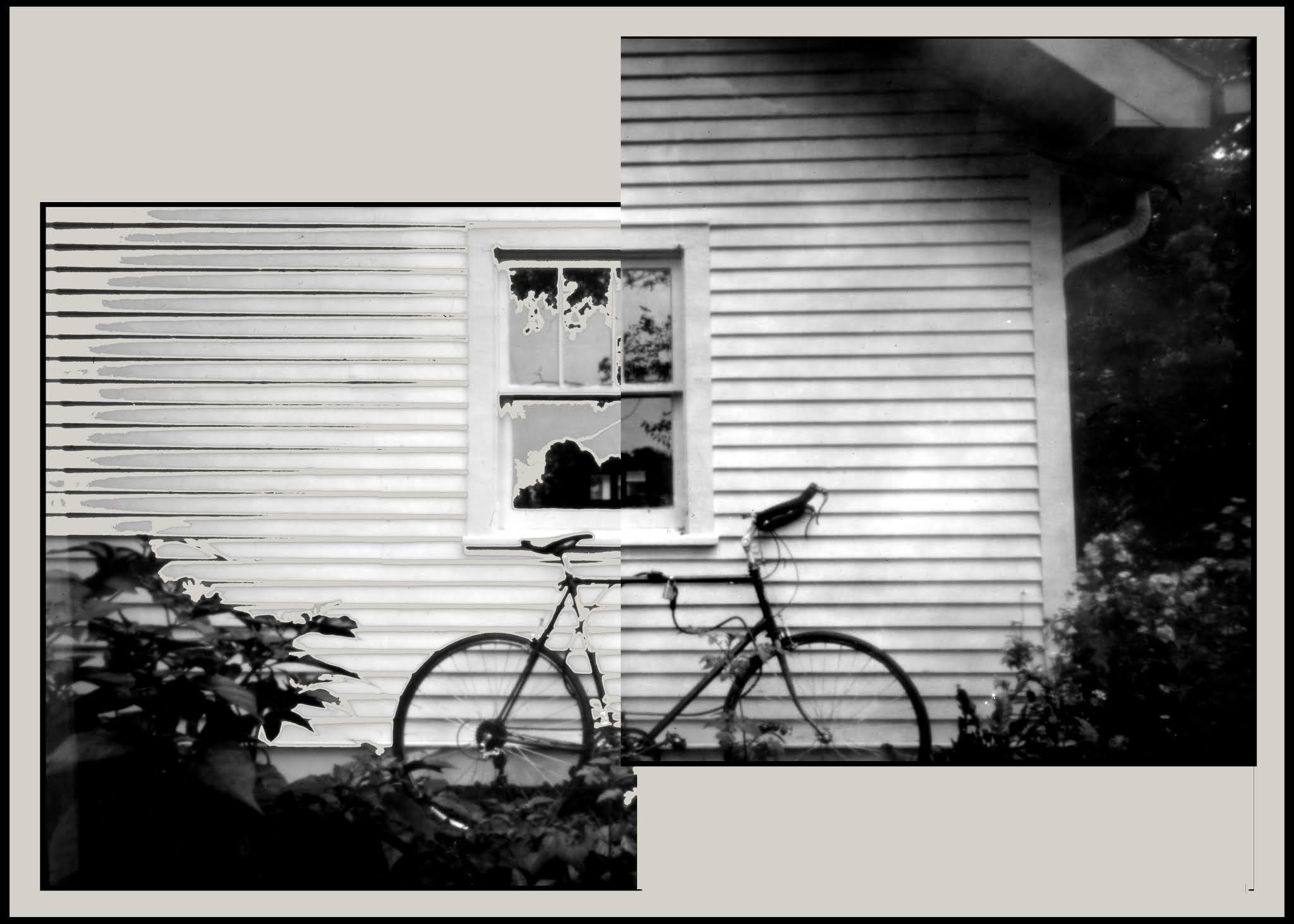
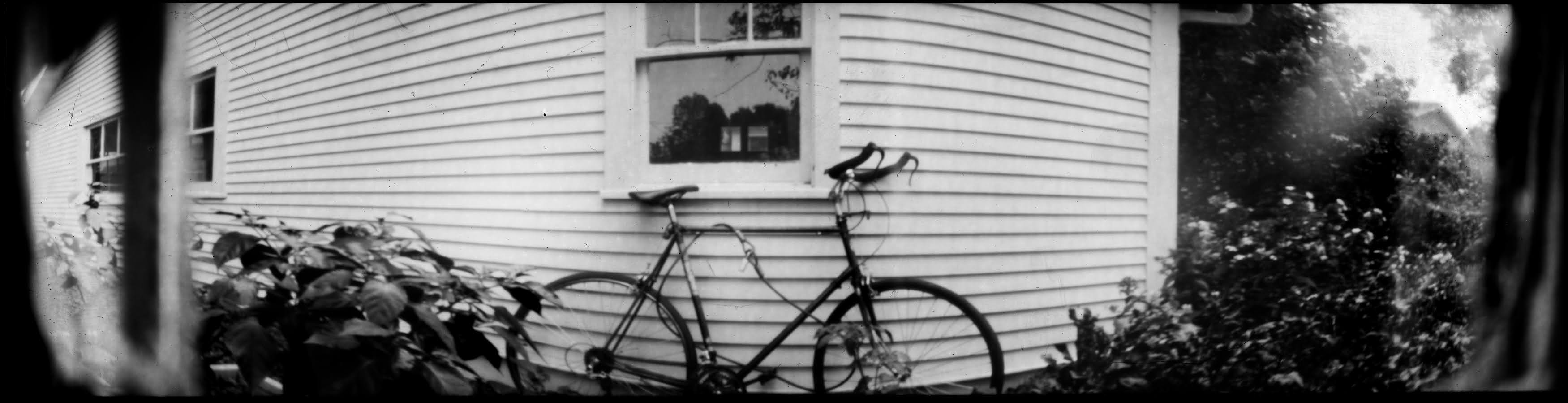
It wouldn’t be a proper experiment if there wasn’t a control condition without using the viewfinder. This is my Takara Standard bicycle which I bought with Gerald Ford’s economic stimulus tax rebate in 1975 and commuted on when there wasn’t snow from 1977 to 2007. Originally it had dropped handlebars. I just had the bull horn handlebars put on it to replace some straight ones I put on after I retired. It looked kind of steam punk with those shiny steel straight bars, but now it looks really Metal. I recently went on the farthest and fastest ride since I was in my thirties on it. Looks like the camera was pointed ever so slightly to the left of where I wanted to be, but probably as good as I would have been with the viewfinder.


Isn’t there a meme somewhere about not messing with an old man on a bicycle? I always seem to get a little closer than I want when I’m going to be in the picture and I don’t think the viewfinder would have helped with that.


I found using the viewfinder was just another thing to have to mess with and it didn’t help me that much to visualize the picture or to more accurately point the camera.  For someone just beginning in pinhole photography I can see how it would help on both these issues and make the transition to the Zen of Pinhole a little easier.

Friday, September 11, 2020

Evolution of the Pinhole Lab Camera


Several years ago I wrote about my fantasy of a rigorous, in-depth pinhole photography class that included building a camera that would allow the student to explore several classic pinhole experiences.

The camera was based on 2.5 x 4 inch paper negatives. That is exactly one eighth of a sheet of 8x10 inch paper. The box had pinholes on two sides, one 4 inches away from the image plane and the other 2.5 inches from the image plane. There were six pinholes to accommodate axial and rising front images at both distances and with the camera oriented vertically or horizontally. With extensions and inserts the distance to the pinhole could be modified to wider or narrower angle of view. With two extensions and inserts, I had a range of distances from 1.25in (30mm) to 8in (200mm). I just used pieces of opaque tape for shutters. It could also accommodate larger 4x4 inch squares on the short side and several lengths of negatives forming differing curves inside of it.


It worked pretty well. I had no problems with light leaks. There were a couple places where improvements could be made. 

The first problem was placing and removing a negative in the removable back for exposures at the longer distance to the pinhole. The paper is held on by tape. Since the box was slightly larger than the paper, it was hard to be sure it was really square and it was hard to get it out without scratching or creasing it. Loading and unloading on the flat short side was much easier. 

Drilling six .5mm pinholes (see below) was pretty easy, but it’s kind of a pain to drill smaller pinholes where they have to be measured and adjusted to be identical. Drilling just three would be half as much trouble. The pinholes were held in a removable mount but it was an odd shape and had to be taped in if you wished to change pinholes.

The new design is also based on the one-eighth sheet size negative. 

Paper negatives have several advantages over film in an instructional setting. It’s cheaper for one thing. That’s not only to accommodate strained school budgets but it also encourages experimentation. It can be handled under safelight and you can see the image develop. There’s a learning advantage to a process where you expose an image, wonder how it worked while getting back to the darkroom and get immediate feedback and reinforcement if it went well.

That negative may seem a little small but it’s bigger than an Instax print or a 6x9cm frame of film. The aspect ratio almost exactly matches standard 35mm frames, smart phones, computer screens and HDTV.

I’ve always made cameras where the back comes off to load light sensitive material, probably because that’s how cameras have been made since the beginning. The new camera is a 2.5 by 5 by 4 inch box with a top that fits over the bottom.


With the original I just used pieces of opaque tape for shutters but kept having trouble overlapping. The shutter I wanted to open was occasionally taped down by the tape of one of the others. This time I made a single and a double sliding shutter and trimmed them so they went together with the openings close together. The shutter handle prevents the slider from going back in too far and pushing the other side when you close it.


The sides of the box have rectangles of triple weight cardstock glued to them which form grooves down the side.


The film holder is a triple weight piece of stock that you can tape the negative to and slide into the grooves at four distances from the pinhole: 1.25 inch (30mm), 2.5 inch (60mm), 3.75 inch (90mm) and 5 inches (120mm).


To demonstrate, I set the tripod up facing my old bicycle leaning against the garage.


I wanted to eliminate variable lighting situations which meant being limited to cloudy conditions. That meant taking precautions because rain kept falling from those clouds. Stray sunbeams would pop in unannounced as well.


At 5 inches (120mm), 43 degree angle of view. 35mm camera equivalent is 45mm.


At 3.75 inches (90mm), 56 degree angle of view. 35mm camera equivalent is 34mm.


At 2.5 inches (60mm), 77 degree angle of view. 35mm camera equivalent is 23mm.


At 1.25 inches (30mm), 116 degree angle of view. 35mm camera equivalent is 11mm. Darn! Looks like the angle of view is now wide enough so the shutter is in the way. I’ll have to work on that.


The reason for the multiple pinholes is to have the basic capability of a rising front of a view camera. This allows you to seem to be getting a higher angle of view without tilting the camera up. It’s most commonly used in architectural photography where it’s very important to keep the vertical lines parallel. When the camera is tilted up, verticals converge toward the top so buildings look like they’re falling over backward. 

In a camera that’s likely to be used without a tripod, it also gives the photographer some flexibility for getting a higher point of view with the camera sitting level on a flat surface. Think of a portrait of a dinner companion across the table without the table surface filling the bottom half of the frame.

What’s essentially happening is that the pinhole is projecting a circular image that’s larger than the negative. With a pinhole above the camera axis, the negative captures a portion of this circle slightly off center. If the camera was level in the first place, your vertical lines are still parallel but you seem to have a higher point of view. With this camera, if you turn it over, it behaves like a falling front to get a lower point of view.

Here’s the axial pinhole at 2.5 inches next to the risen pinhole at the same distance.


Here’s the whole picture with the risen pinhole. I’m afraid this isn’t the best illustration because if you look at the corner of the garage, you’ll see the tripod platform wasn’t perfectly level and the camera is tilted up a little. What’s also not so obvious is the top of the image is now farther from the center of the pinhole so there’s an exposure gradient. The top of the image is now underexposed a little compared to the bottom.


This is an example of the axial pinhole with the camera tilted up. If you measure you can tell the angle of the side of the garage is more extreme and the window is more trapezoidal. I’ll have to do a better illustration of this in a future post.


The camera has no tripod mounts because it’s intended to be placed in different orientations. It’s easy to make a platform to attach it to with rubber bands if you do have a tripod. 


Of course all these shenanigans work in the vertical orientation as well.


Another feature of the camera is a simple, removable mount that slides into a groove at the front of camera making it very easy to change pinholes.


I started with .54mm pinholes made by completely piercing sheet brass with a #10 quilting needle and sanding off the burr. I chose this size because it’s so easy to make them. I have seen hundreds of people as young as 8 years old make a perfect pinhole this size on the first try. Making three is really no trouble. For the old camera, I had made about 18 in a row in about a fifteen minute period. I didn’t measure them, I just looked at them with a 10x loupe and they seemed OK.


I pulled three off one of the old cameras. Out of curiosity, I looked at them with the USB microscope.


Looks like that third one isn’t that beautiful. I had already attached them to the mount. Looking back at that picture through the loupe, it ended up being the one on the axis.

In order to demonstrate the changeable pinhole capability, I drilled three .3mm pinholes. This is trickier than completely piercing the metal but it’s not that hard. Again less than fifteen minutes went into this. The nearest thin cardboard was a movie ticket I had found in a pocket from last winter. (Beforetimes, ya know). One layer as a spacer under the brass gave me a .2mm hole so I folded it double and made these three in a row at .3mm, within one percent of each other.


The first five pictures above are with the .54mm axial pinhole, and the rest are with the .3mm pinholes. Did you notice the difference?

You know you love this sort of thing so here’s a detail from the negatives comparing the pinholes at each distance - .3mm on the left and .54 on the right. (This is with that slightly oval .54mm pinhole).

At 1.25in (30mm).  Mr. Pinhole says .238mm is optimal.


At 2.5in (60mm).  Mr. Pinhole says .336mm is optimal.


At 3.75in (90mm).  Mr. Pinhole says .412mm is optimal.


At 5in (120mm).  Mr. Pinhole says .475mm is optimal.


Keep in mind that optimal sharpness is not necessarily an objective. Shorter exposures or a generally softer look may be what you want.

I wrote the f ratios of all the combinations on the top of the camera. I used Pinhole Assist to measure the exposures. Since there’s no reciprocity failure with paper, you could use any light meter app that went down to ISO 5 and up to f400. It would be a good exercise for your students to calculate a Sunny-Bright-Cloudy-Overcast table, paste it on the camera and use that to determine exposures.


Curved image planes and panoramas are favorite options with pinhole photography. A 6.25 or so inch strip will curve into an almost perfect 2.5 inch radius, almost a 180 degree angle of view.


Again with that shutter in the way.


A 10 inch piece of paper will give you a curve that varies from 2.5 to five inches.  The pinhole really doesn’t care.


It’s half the angle of view vertically but again almost 180 degrees horizontally, if it weren’t for the darned shutter. There must have been a bit of a gap between the pinhole mount and the front of the camera. You can see the little division and the other opening at the left. Doesn’t it seem like the image of that second window looks misaligned on either side of the divider? How did that happen?


I found a lot of little errors and adjustments needed to be made in the template. 

The box was exactly 2.5 inches high. I kept cutting paper slightly too wide so it would curl when I closed the top on it.  I had to trim a tiny strip off almost every one of these negatives. I’ll have to leave a little gap to account for imperfect paper cutting.

Also there’s that darn shutter on the widest angle. I have to say that if you were only going to use the axial pinhole a tape shutter would be fine. I have done it with three tape shutters but as mentioned earlier that requires a bit of care. I think I can make the openings a little bigger and eliminate at least one layer in the shutter. I’ve always made the shutter with a front and back with the sliding part between them so I could have a finished working shutter before gluing it on the box. You could however just use the front of the box for the back of the shutter. That would bring the sliding shutter that much closer to the pinhole. Cutting the parts with beveled edges might also do the trick.


This new design doesn’t allow for the longer distances to the pinhole beyond 5 inches but I seem to be the only one interested in that sort of thing. It doesn’t allow for the larger square format negatives although, you could easily put holes in the top and get an almost 4x5 inch negative taped to the bottom.

I’d love to get some feedback that I could incorporate to improve things. 

I’ll make the changes to the template, build a new one and take it out in the field in a future post.